Vertical Heat Exchanger,Heat Exchanger,Heat Cooling Exchanger,Double Coils Exchanger Dandong Huarui Fluid Machinery Co., Ltd , https://www.ddhrseal.com

How to solve the phenomenon of shadow smear on LED display
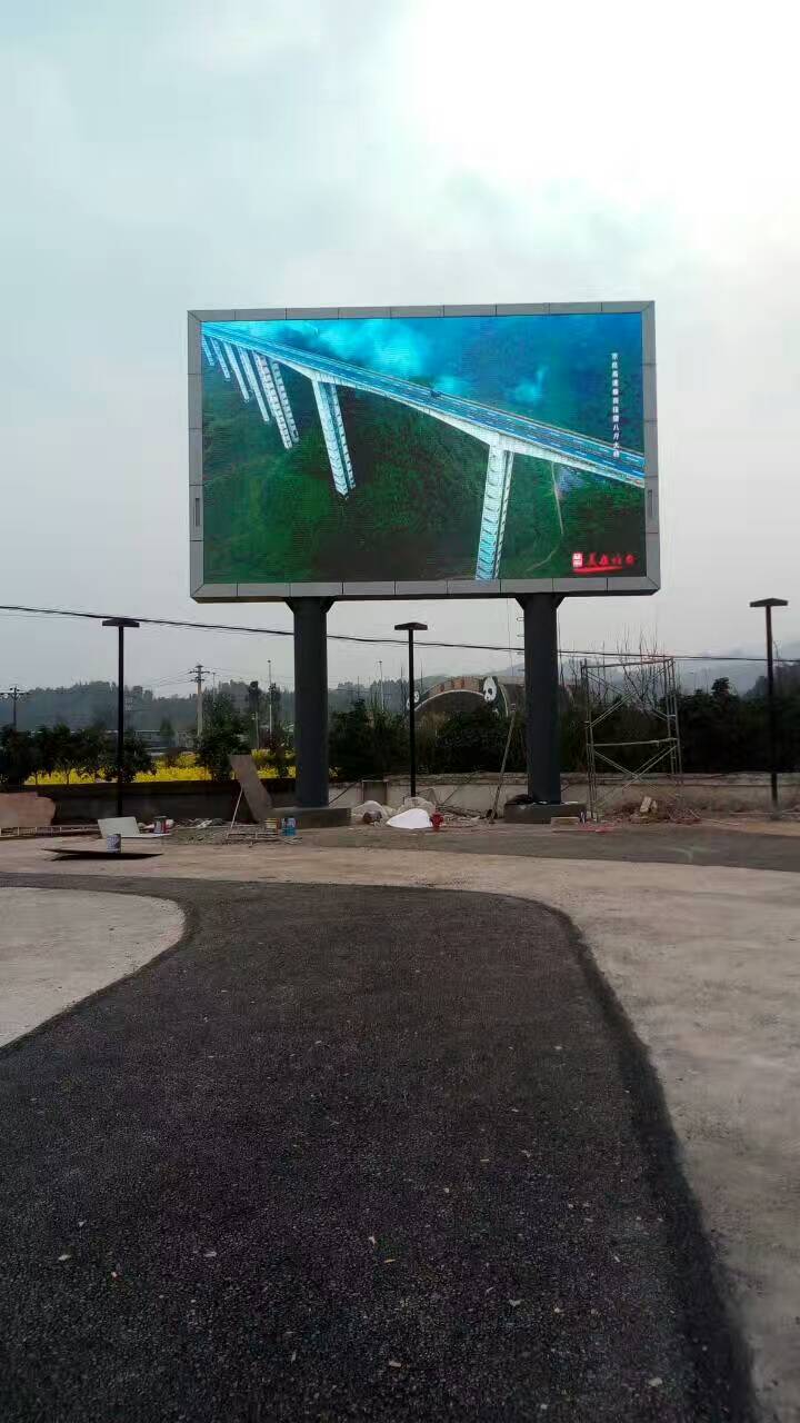
LED full-color display in the operation process, from time to time there will be such a problem, and the problem of display tailing is that we often see the problem, the appearance of smearing is controlled by the LED display-driven scanning .
1/4 sweep LED display schematic. The working principle is that each line of power V1-V4 within one frame of image is turned on for 1/4 of the time according to the control requirements. This has the advantage of more efficient use of LED display features and lower hardware costs. The disadvantage is that within one frame of the image, each line of LEDs can only show 1/4 of the time. For example, when the frame frequency is 50Hz, the display time per line is Tm=1000/(50×4)=5ms. If a higher frame rate or the number of scanning stages is further increased, the display time will be shorter, such as 50Hz. Frame rate, 1/16 scan, Tm = 1.25ms. As Tm becomes shorter, the quality of the rising and falling edges of the row power waveform will be critical to the normal operation of the system.
2, problem analysis
The working principle of the scanning display has been described in the foregoing, and the ideal waveform of the 1/4 scanning line power supply has been described. However, in practice, its waveform is far from ideal. Figure 3 is a waveform diagram using the 4953 as a row power switch control. Due to the 4953 natural defect, it is used as a row power supply control switch, and its falling edge Tf will be greater than 100μs. If the row power rising edge time is ignored (in fact, the rising edge time is negligible), it is not difficult to see that in 1 Within the frame image, the previous line and the subsequent line will have an overlap time of about 100 μs. To facilitate the analysis and calculation, we can approximate the overlapping time Tn as the falling edge time Tf. Namely, Tn=Tf.
In this way, when the second line should be displayed, the previous line will still glow with the control of the second line for a period of time in Tn. In our vision, the previous line will be slightly bright. The magnitude of the brightness is proportional to the ratio of the overlap time of two lines to the display time, ie, proportional to Tn/Tm. Here we define Tn/Tm as the overlap ratio, also taking the 50Hz frame rate as an example, Tn/Tm=0.1/(1000/(4x50))=2%. It seems that the overlap ratio of 2% is not very large. However, as the frame rate increases or the number of scanning stages increases, the overlap ratio Tn/Tm will greatly increase.
Now we can increase the frame frequency to 250Hz and look at it again. At this time, the line power switch control waveform is shown in Figure 4. It is clear that the overlap ratio at this time reaches Tn/Tm=0.1/(1000/(4×250)). =10%. Under such a high overlap ratio, the trailing phenomenon will be very obvious.
3, solution
Above we analyzed the trailing principle of the scanning LED display. Therefore, to solve this problem, we must start from the source and we must reduce the overlap ratio. However, due to the 4953 natural defect, the falling edge of the line power could not be reduced by the 4953 itself anyway. One method is to add an absorption circuit. The effect of this external absorption method is closely related to the cost involved. To achieve good results, it is necessary to add more complicated lines, which not only increases the cost of the entire machine System wiring brings a lot of inconvenience and trouble.
Obviously, using the D4963 is nearly 1000 times less than the existing 4353 falling edge. The application is basically the same as the existing 4953, and no additional components are allowed. This makes the design of the scanning display more flexible, and the number of scanning stages can be greatly increased without sacrificing the frame frequency, which will greatly save the cost of the entire machine. We use 1/32 scanning as an example. If the frame frequency is set at 250Hz, only the overlap ratio is Tn/Tm single parameter, Tn/Tm = 0.0001/(1000/(32x250)) = 0.08%. There is no doubt that the bottleneck problem of LED scanning display tailing in this case will be fundamentally improved.
From the above analysis, it can be seen that the scanning reduces the overlap ratio, the absorption circuit can be added to reduce the tailing phenomenon, and the appropriate matching of the application methods makes the design of the LED display screen flexible and changeable. In addition to the operator's application methods, The design of the LED display itself is also the main reason to solve the smear.