Stamping is a manufacturing process that involves applying pressure to a material to deform it into a desired shape or size. There are various types of stamping processes utilized in the industry, each with its unique set of advantages and disadvantages. In this article, we will describe some of the most common types of stamping processes.
Overall, stamping is a versatile manufacturing process that plays a crucial role in the production of a wide range of metal parts and components. By understanding the different types of stamping processes, manufacturers can select the most suitable process for producing high-quality parts in an efficient and cost-effective manner.
hardware stamping products, stamping part products, Precision Metal Stamping, precision metal stamping part, Stamping Processing Products NINGBO CITY YINZHOU RUICAN MACHINERY CO.,LTD , https://www.nbsandcasting.com
Overview At present, 300 MW and above units, whether domestic or imported, use DCS without exception. Even 200MW and 100MW units are using DCS to retrofit. Even the 25MW and 12MW thermal power units of some captive power plants also use DCS. system.
Then, as the practical application of the 1990s, the fieldbus control system (FCS), the newest type of control system in the field of automation, can be accepted and widely used by power plants like DCS systems. 
1. The most significant features of FCS and DCS
According to the definition of the International Electrotechnical Commission IEC1158, a digital, serial, and multi-point communication data bus installed between a field device in a manufacturing or process area and an automatic control device in a control room is called a field bus. 
The fieldbus-based all-digital control system is called the fieldbus control system FCS. That is: Fieldbus is an open, fully digital, two-way communication and multi-station communication system used between field instruments and control room systems. 
The specific comparison between DCS and FCS is as follows:
(1) The DCS system is a large system, its controller function is strong and its role in the system is very important, data highway is the key to the system, so the overall investment must be in one step, and it is difficult to expand afterwards. The FCS function is thoroughly decentralized, and information processing is on-site. The widely used digital intelligent field devices make the function and importance of the controller relatively weak. Therefore, the FCS system has a low investment starting point and can be used, expanded, and put into operation. 
(2) The DCS system is a closed system, and the company's products are basically incompatible with each other. The FCS system is an open system, users can choose different manufacturers, different brands of equipment connected to the field bus, to achieve the best system integration.
(3) The information of the DCS system is all formed by binary or analog signals, and must have D/A and A/D conversion. The FCS system is fully digital, eliminating the need for D/A and A/D conversion and providing high integration and high performance, which can increase the accuracy from ±0.5% to ±0.1%.
(4) The FCS system can incorporate the PID closed-loop control function into the transmitter or actuator, shortening the control cycle and can now increase from DCS 2 to 5 times/s to FCS 10 to 20 times/s. Improve regulation performance.
(5) The DCS system can control and monitor the entire process and diagnose, maintain and configure itself. However, because of its own fatal weaknesses, its I/O signals use traditional analog signals, which make it impossible to remotely diagnose, maintain, and configure field instruments (including transmitters, actuators, etc.) on the DCS engineer station. The FCS system uses all-digital technology, and the digital intelligent field device sends multi-variable information, not just univariate information, but also has the function of detecting information errors. The FCS system uses a two-way digital communication fieldbus signal system. Therefore, it can remotely diagnose, maintain, and configure field devices (including transmitters, actuators, etc.). This superiority of the FCS system is unmatched by the DCS system. 
(6) Since FCS systems are on-site for information processing, compared with DCS systems, a considerable number of isolators, terminal cabinets, I/O terminals, I/O cards, I/O files, and I/O cabinets can be eliminated. At the same time, it also saves space and floor space for I/O devices and equipment rooms, and some experts believe that it can save 60%.
(7) For the same reasons as (6), the FCS system can reduce a large number of cables and bridges used for laying cables. It also saves design, installation and maintenance costs. Some experts believe that 66% can be saved.
For the points (6) and (7), it should be added that the use of the FCS system to save investment is unquestionable, but whether or not it is said by some experts that 60% to 66% has yet to be objective Evaluation, although these figures appear in many articles, the author believes this is the result of mutual transfer, and the original source of these numbers has not yet been found. Therefore, readers should be cautious when referring to these figures.
(8) FCS has a simple configuration with respect to DCS. Due to its standard structure and performance, it is easy to install, operate, and maintain. 
(9) FCS design development points for process control. This is not a comparison of DCS. It only shows the issues that should be considered in the design and development of FCS for process control or for simulating continuous process.
1) The requirement for intrinsically safe explosion protection of the bus is of primary importance. 
2) Basic monitoring such as flow, material level, temperature, pressure, etc. is slow, but also has hysteresis. Therefore, node monitoring does not require fast electronics response time, but requires complex analog processing. ability. This physical characteristic determines that the system basically uses a centralized polling system between master and slave. This is technically reasonable and economically advantageous. 
3) Measurement of flow, material level, temperature, pressure and other parameters, the physical principle is classical, but sensors, transmitters and controllers should be digital intelligent development. 
4) As an FCS system developed for continuous processes and their instrumentation, emphasis should be placed on the design of the low-speed bus H1. 
2. Practical application of FCS in thermal power plants
Fieldbus control system FCS is a new type of control system. The time to enter China is not long, and the application in thermal power plants is still in the stage of local field use. 
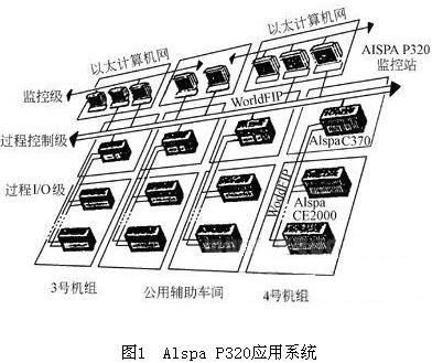
Example 1: The Cegelec Alspa P320 system (see Fig. 1) is applied to the automatic control of China Huanengqi Power Plant (4×360MW) Phase 2 (2×360MW) units. The system has 31 dual redundant WorldFIP networks, 16 monitoring and control stations, 32 redundant PLCs, processing 18000 I/O points, and 50,000 control data. The system uses twisted-pair media. The operation station is redundant and has a backup station. The typical response time of the system is 50ms. 
The second phase of Huanengrong Power Plant is a 2×360MW coal-fired generating unit introduced from the full set of French GECALSTOM Group. The boiler was supplied by STEIN, the steam turbine was supplied by STG, and the generator was supplied by STG. All of the power generation control systems that were put into operation at the end of 1998 were provided by the French company CEGELCE and developed and launched in the mid-1990s as ALSPAP 320 control systems. The main functions of the unit's DAS, MCS, SCS and BMS are realized. The digital electrohydraulic control system (DEH) of the steam turbine adopts the MICROREC control system provided by the French company GECALSTOMSTG. 
Each part of the ALSPAP320 control system communicates with each other through a standard network, and can communicate with other control components conveniently. ALSPAP320 has three major networks:
The LOCAFIP Fieldbus Network (WorldFIP) uses the FIP standard (UTEC64+601607) to link input and output templates to the P320's C370 controller. 
F900 data bus (WordlFIP) for data exchange between C370 controllers and C370 controller for communication with CENTRALOG. The F900 is a fast data transmission network based on the industrial LAN of the IEEE FIP standard (UTEC64+601607).
The CONTRONET control network uses Ethernet technology for centralized data exchange between the control layer CENTRALOG database and the operator station. CONTRONET complies with the IEEE803.3 LAN standard. 
Through the INTERENT standard protocol, the P320 can perform long-distance communication for remote maintenance and large-scale power grid control. 
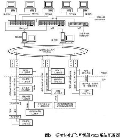
Example 2: Shaanxi Yangling Gas Turbine Thermal Power Plant is located in the Yangling Agricultural High-tech Development Zone in Shaanxi Province. The Simatic PCS7 control system based on the Profibus fieldbus protocol produced by the German Siemens Company is used as a centralized control system for the furnace, furnace and electricity. 
A total of three pairs of redundant CPU-41H controllers are configured in this system. Each pair of redundant controllers has a number of remote I/O extension racks ET200M and I/O modules via redundant fieldbus Profibus-DP (up to 12Mbit/s for the latest data rates). Remote I/O stations consisting of remote I/O extension racks and modules are placed near the site and communicate via a Profibus-DP bus with a redundant controller placed in the main control building.
The system is equipped with a total of 32 ET200M remote racks, divided into 8 remote I/O stations according to the process flow, placed in 8 different locations of the whole plant, and the remotest remote I/O station - Sham Tseng pumping station remote I/O The distance from the main plant area is about 3.4 km, and the distance between other remote I/O stations is within 200 um. The communication between the controller and remote I/O stations is accomplished through the Profibus-DP fieldbus. The Profibus-DP fieldbus transmission medium in the main plant area is twisted pair, and the remote I/O station and the main plant interval  Data communication adopts optical fiber as the transmission medium. Both ends are connected through the photoelectric conversion interface and connected with the Profibus-DP field bus. 
Due to the use of Profibus-DP field bus technology, the I/O cabinets are arranged on-site to realize the peripheral equipment for the gas turbine, waste heat boiler, auxiliary engine for the turbine, circulating pump room, integrated pump room, pumping station for the deep well, and electrical system for the factory, 110 The system such as the kV booster station exchanges bidirectional data with the server of the master control ring, and realizes centralized monitoring of all systems in the whole plant. The automatic system investment rate reached 100%. In August 2001, the system was put into commercial operation. 
Example 3: Sichuan Guang'an Power Plant, using L2-DP network technology that conforms to Profibus fieldbus protocol, successfully interconnected the boiler make-up water control system with the auxiliary workshop control system such as condensate polishing process control system control, and improved the auxiliary workshop control of thermal power plants. Labor productivity and system reliability.
3. Local application effect of FCS in thermal power plants
First clear three key points of FCS:
(1) Core: The heart of the FCS system is the bus protocol, the bus standard. In other words, only the fieldbus-based control system can be called a fieldbus control system. 
(2) Foundation: The foundation of the FCS system is the digital intelligent field device. The digital intelligent field device is the hardware support of the FCS system. 
(3) Essence: The essence of the FCS system is the on-site information processing. This is a manifestation of the effectiveness of the FCS system. 
Let us analyze a few examples of FCS applications mentioned above for thermal power plants. 
In Example 1, the ALSPA320 control system of Huaneng Power Plant, its LocaFip network and F900 network both follow the WorldFip fieldbus bus protocol, and the CONTRONET control network uses Ethernet technology. This is a very typical fieldbus architecture.
In Example 2, the Simaeic PCS7 control system of the Yangling Thermal Power Plant and the communication between the controller and each remote I/O is accomplished through the Profibus-DP fieldbus. Data communication between the controller and the controller and between the controller and the server is accomplished through redundant ring-type industrial Ethernet. 
In the above two examples, the fieldbus protocol is followed in the communication network, that is, they all contain the core part of the fieldbus control system. However, another common feature is that no digital intelligent field devices are used, and analog measurement elements are still used. The implementing agency does not have on-site control functions. Without the hardware support of the fieldbus control system, the on-site information processing cannot be realized. That is to say, the outstanding characteristics of the fieldbus - reducing system investment costs, reducing operating costs, and improving operation and management levels, have not been fully realized. Case 3 is a successful example of fieldbus in local applications of thermal power plants. 
4. Application Prospects of FCS in Thermal Power Plants
(1) Fieldbus control system is the latest type of control system. It is a new type of computer-based, all-digital, two-way communication control system. Fieldbus technology brings a revolution to automation and represents the direction of automation. Digital communication is a trend and it is also an inevitable development of technology. In theory, the two-way digital communication field bus signal system technology will surely bring real benefits to the safe and economic operation of thermal power plants and improve the management level. This is unmatched by any control system used in power stations in the past. 
(2) As the core part of the fieldbus control system, the bus protocol has been successfully operated in the communication network of the thermal power plant control system. This not only eliminates many of the doubts previously held by people, but also the field bus control system in the thermal power plant. Promotion and application laid a good foundation. 
(3) The field bus control system can achieve maximum benefit in the networking control of the auxiliary shop control system of a thermal power plant based on sequential control and PLC (programmable logic controller) as the hardware (see Example 3). As a station, PLC hangs on the high-speed bus, giving full play to the PLC's advantage in handling the switching direction. The application of fieldbus in this field has been successful. This will be an optimal solution to achieve a moderate centralized control policy for the auxiliary plant of thermal power plants in the coming period of time. 
(4) Since there are few varieties of digital intelligent field devices that can meet the thermal power plant control requirements at present, theoretical field bus benefits cannot be fully realized. Therefore, the time to fully adopt a typical fieldbus control system on a large-scale unit is not yet ripe. 
(5) At present, the control systems like the example 1 and the example 2 are a transitional control system to the FCS. It not only retains the powerful controllers and I/O modules in the DCS system, but also communicates. The network follows the fieldbus protocol. We refer to this system as a digital decentralized control system that follows the fieldbus protocol in the direction of communication and data transmission. We call this system temporarily the FDCS.
Blanking: Blankings are flat pieces of sheet metal that have been precisely cut and punched out from larger sheets of metal. Blanking is a process used to produce these flat pieces, and is ideal for producing large quantities of uniform, flat parts.
Coining: Coining is a stamping process used to create impressively flat and precise features - often used in creating coins or bearing seals.
Drawing: Drawing involves pulling a flat piece of metal through a die with a punch tool to form it into a three-dimensional shape. This process is commonly used in the creation of products such as automobile fenders, cans, and ship hulls.
Embossing: Embossing is the process of applying raised designs or patterns to a flat piece of metal by impressing the metal with a die. This process is popularly used in the production of decorations and signage.
Piercing: Piercing is the process of punching or drilling holes in a metal sheet. It is widely used in creating products such as luggage tags, name plates, and metal attachments.
Blanking and forming: Blanking and forming involve using a single die to create a part that has a variety of features, both flat and formed. It is a highly efficient process for creating complex parts.

Application of Fieldbus Control System in Power Plant
Abstract: In the 1980s, DCS (Digital Distributed Control System) began to enter the field of automatic control of power plants. Because of its positive effects on safety production and economic benefits, it was impossible for any control system in the past to be compared with it. DCS is widely used at power stations.
The system configuration diagram is shown in Figure 2.