Pre-set discussion on gear frame drawing
Design Calculation Module This module is used as the main program of the system. The programming frame is designed according to the traditional manual design process of the gear mechanism, so that the students can easily understand and master. In this system, the calculation program has been compiled, the user only needs to input relevant data according to the prompt, the system can calculate and output the result data, and the result can be called as a drawing parameter, so as to realize the calculation drawing.
Output data module 1. Generate calculation instructions using QBASIC sequential file-specific statements, store the design calculation process and results in the data file sms.dat.2 according to the format of the calculation specification. The drawing parameters are stored in the data file and still use the sequential file of QBASIC. The statement stores the parameters to be called in the data file cs.dat. There are two points worth noting: the order in which the drawing parameters are stored is the same as the order in which the drawing module takes the parameters. AutoLISP reads the data of the data file line by line, and assigns the data to the variable, so the data should also be stored one by one.
The drawing module uses three different methods to write the drawing module. This highlights the variety of ideas and methods, and also allows students to have a better understanding of computer graphics. 1. Written in AutoLISP language. The program takes the drawing parameters in the data file cs.dat and draws it in AutoCAD. For example: fetch the data and assign it to the variable mn (modulo): (setqMn) In order to simplify the program, set the operating environment to modify AutoCAD with the Au-toLISP function. System variable. For example: set the current layer to RED, the current line type is DASHED: (setvarclayerread) (setvarceltypedashed) AutoLISP's internal function is very rich, students are difficult to grasp, we instruct students to use AutoLISPCOMMAND function to call AutoCAD commands, so, the operating parameters that need to be provided It is also the same as the standard commands for operating AutoCAD.
2. Use the AutoCAD command group file. Using the QuickBA-SIC sequential file-specific statement, the drawing commands and response sequences of the gear drawing are sequentially stored in the format required by the SCR file with the PRINT1 statement. Generate an SCR file. In the AutoCAD, use the SCRIPT command to call the SCR command group file to achieve automatic drawing. In order to realize the design drawing, the drawing parameters of the data file cs.dat are still read out by the AutoLISP statement.
3. Use QuickBASIC drawing. Using QBASIC screen control and drawing instructions, the gear work diagram is written in the response sequence in the drawing sequence. Note that the thickness of the line is represented by color, and the drawing parameter value is directly transmitted by the variable of the main program. Drawing graphics in the QickBASIC programming language gives students a clear understanding of how the basic low-level drawing actions of the drawing software are performed.
Implementation of the design drawing system Because the system module involves two systems, QuickBASIC and AutoCAD, in order to realize the design drawing, it needs to run in one system, that is, in the AutoCAD system. We debug all the programs CLJG.BAS that integrate each module (except the drawing module), then compile it into the CLJG.EXE program, and then execute it in the DOSCOMMAND state of AutoCAD. According to the menu prompt operation, the computer can complete the design calculation of the gear mechanism, and automatically save the relevant drawing parameters into the cs.dat file. Finally, execute the LSP or SCR file in the COMMAND state of AutoCAD and draw the gear working diagram. This achieves the design drawing.
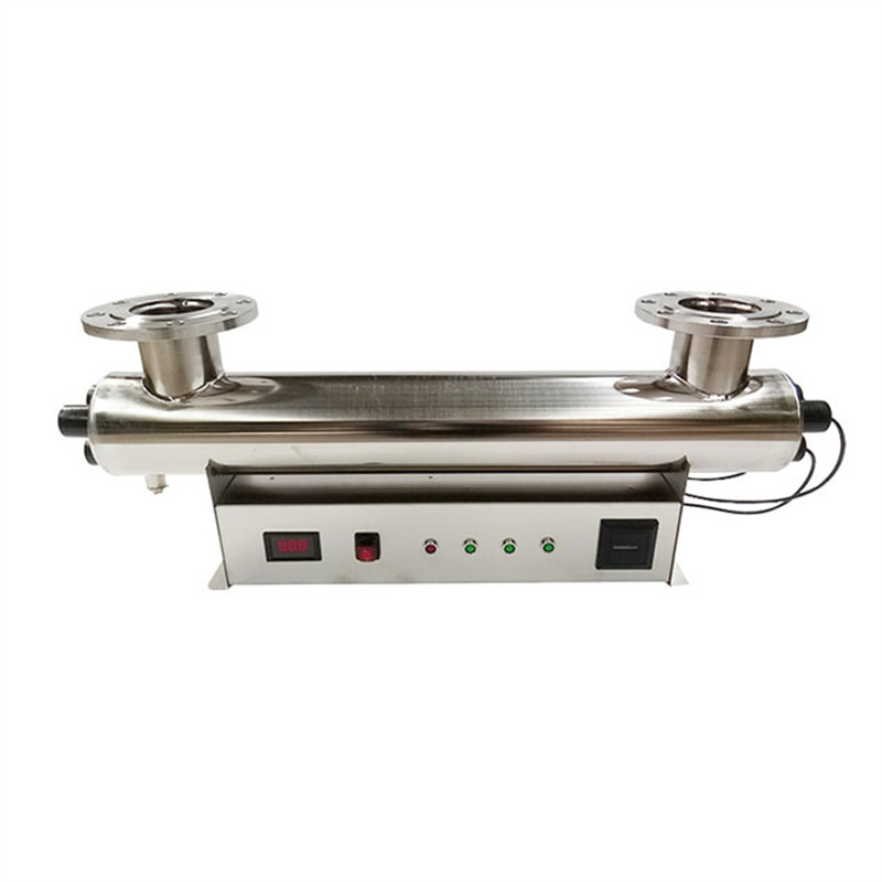
UV Sterilization
Product Details
* high purity quartz tube
*appropriation uv lamp tube for water *treatment sterilization strong,long lifetime,
*stable and reliable operation,
*It's bactericidal efficiency is more than 99.9%.
*Lamp lifetime is more than 8000 hours.

UV is a very cost-effective and a reliable technology that protects the public against pathogenic microorganisms, including protozoa, bacteria and viruses. Chemical disinfection using chlorine is also effective against these pathogens; however, there are pathogens, such as Cryptosporidium and Giardia, which are chlorine-resistant but can be disinfected by UV ligh
UV Sterilization,UV Sterilizations,Swimming Pool Sterilizer,Wastewater UV Sterilization,High efficient UV Light Sterilizer
YIXING HOLLY TECHNOLOGY CO.,LTD. , https://www.watertreatment-machine.com