Digital Printing,Cotton Nylon Fabric,Solid Color Fabric,Cotton Poplin Fabric Shaoxing MingFang Textile Co., Ltd , https://www.printings-fabrics.com
1.2 FOUNDATION Fieldbus Features The most important feature of the FOUNDATION fieldbus is the use of functional blocks in field instruments and equipment, ie the use of functional blocks directly on site to build specific control systems. So FOUNDATION fieldbus is not only a signal and communication standard, but also a system standard. The FOUNDATION fieldbus function block and the function blocks used in the PLC/DCS have certain differences. It is an independent application system. Each function block has a variety of parameters that can be configured.
1.3 Foundation Fieldbus Control System Test 1.3.1 Composition of Fieldbus Test System In order to study the engineering application characteristics and performance of the FF fieldbus, a basic and complete FCS control system was constructed, including the SmarSystem 302 system (FF fieldbus). Gateway bridge controller (DFI302), FF transmitter, FF valve positioner, host computer, and bridge controller are linked to HSE through HUB. Among them, the gateway bridge controller serves as a gateway link device between HSE and H1 and a bridge between different H1 branches, and also serves as a system controller. The actual wiring of the FF fieldbus test system is shown in Figure 1. 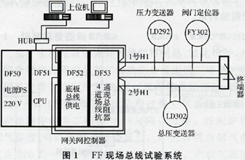
The number of H1 bus-connected devices is limited to the following four points: (1) Power supply limitation; (2) Operation speed limit; When the device running time is less than 250ms, one H1 bus can be connected to four field devices; (3) Limit of danger level . If a device on the H1 bus is faulty or damaged, it may cause heavy losses to the enterprise. Such a device can only be connected to one; (4) Bus communication cycle.
1.3.2 Communication Mode of H1 Bus The scanning cycle of H1 bus is divided into macro cycle and monitoring cycle. A macro cycle consists of a so-called background communication cycle and a control scan (operation) cycle. The control scan (computation) cycle completes the link communication between the functional blocks of all nodes on the bus, and the background communication completes the information exchange between each node and the operation station. After a number of macrocycles, all nodes and the operating station complete an exchange of information, known as the monitoring cycle. Macro cycle time consists of link communication and function block execution time and background communication cycle, which is generally a few hundred milliseconds. The monitoring cycle requires (1 to 2) seconds. Background communication cycle can be adjusted. Background Communication cycle extension will lengthen the macro cycle, but it may shorten the monitoring cycle. Because fewer macro cycles can update the data that the bus uploads to the operator station. The Hl bus is slow and is only suitable for slow process control.
1.3.3 Configuration and Operation Test In the test system of Figure 1, two tests were performed respectively;
Test 1: 2 devices on the No. 1 H1 bus form a closed-loop control loop and configure 4 function blocks; 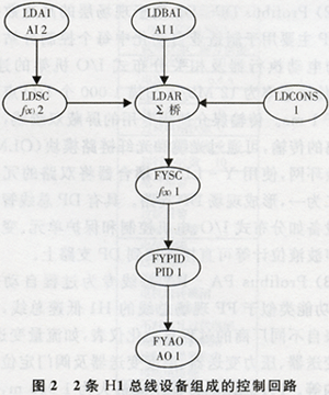
Test 2: 3 devices on the No. 1 H1 and No. 2 H1 buses and the bridge controller form a closed-loop control loop, and 8 function blocks are configured; among them, the No. 1 H1 bus device has 5 functions installed in the configuration. The blocks, 2 H1 bus devices are configured with 2 function blocks, and the bridge controller DFI302 is also configured with 1 function block. The test 2 configuration is shown in Figure 2. In the figure: Numeral 1 indicates that the function block is downloaded to the field device hung on the No. 1 H1 bus; the numeral 2 indicates that the function block is downloaded to the field device mounted on the No. 2 H1 bus; "bridge" indicates this function The block is placed in the CPU of the gateway bridge controller; AI is an analog input; LDCONS is a constant setting; ∑ is an adder; f(x) is a function; PID is a regulator; AO is an analog output. The test results are shown in Table 1. 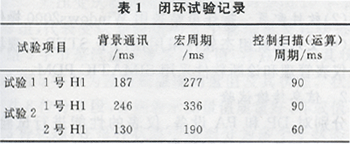
1.3.4 Analysis of application characteristics In the above-mentioned tests, on-site process information collection and simple closed-loop control systems were dispersed into on-site smart meters and devices to achieve a thorough function dispersion and risk distribution. About 73% of the functions of the thermal power plant control system can be distributed to the site, which will greatly reduce the load on the controller, which can reduce the number of controllers and reduce the investment in the control system. The test shows that the speed of the H1 bus is low. In order to transmit non-real-time information such as status and diagnostics, the macro cycle of the bus communication may be greater than 250 ms. Comparing tests 1 and 2 shows that if a device on the H1 bus is unchanged, the control period does not change, but if the number of configuration of the function block is different, the background communication cycle is also different and the macro cycle will change. Therefore, single-loop thermal control objects with slower dynamic characteristics can be distributed to devices on the H1 bus for control. For the system that distributes the control loop function to multiple H1 buses, the calculation of the macrocycle is to calculate the macrocycle of the control loop according to the longest H1 bus of the macrocycle. Therefore, it is better to use a device on the H1 bus to complete the control of a loop. For example, if multiple H1 bus devices are used to jointly control a loop, not only the macro cycle is increased, but also the bridge controller needs to intervene, which will reduce the number of loops. The degree of functional dispersion.
Second, Profibus Fieldbus (ProcessField-bus) Application Research 2.lProfibus Fieldbus Overview Profibus fieldbus is a PLC-based, standardized, fully open bus, can be different manufacturers but follow the same protocol specifications of the instrument, equipment links Make up the system. The Profibus fieldbus consists of the following 3 parts.
(l) ProfibusFMSFMS is a token-structured real-time network. At present, most of the domestic practical applications use 100Mb/s industrial Ethernet instead.
(2) Profibus DPDP is used for high-speed data transmission at the field level. DP is mainly used for the connection of controllers and electric actuators and related distributed I/O racks in each control substation in manufacturing automation. The transmission rate of DP is 12Mb/s, and the time for scanning 1000 I/O points is less than 1ms. The transmission medium uses a dedicated shielded twisted pair cable. For long-distance transmission, a redundant ring network can be formed by the optical fiber cable and the optical fiber link module (OLM), and the two-way redundant optical ring can be combined into one using a Y-LINK coupler. , form a field DP branch. Devices with DP bus smart interfaces such as distributed I/O, motor control and protection units, frequency converters and ultrasonic level gauges can be connected directly to the DP branch.
(3) Profibus PAPA bus is designed for process automation. Its function is similar to the Hl low-speed bus of FF field bus. It is used to connect process automation instruments from different manufacturers, such as flow transmitters, level transmitters, pressure transmitters. , temperature transmitters and valve positioner actuators. The maximum transmission distance of the PA bus is 1900m. The transmission medium is twisted-pair, bus-powered, and has intrinsic safety features. The PA bus is connected to the upper DP bus through the DP/PA coupler, and the process information is transmitted upward through the DP bus.
2.2 Profibus fieldbus cyclic data communication and acyclic data communication Profibus fieldbus master station using token communication, master and slave station master and slave polling communication. Master and slave communications are divided into cyclic data communications and acyclic data communications.
(1) Cyclic data communication Real-time data such as control commands, main operating status data, and process parameters exchanged between the master and slave stations are guaranteed to be transmitted in each communication cycle. This data is defined by the device description file (GSD file) or profile specification file (EDD file), and some of them can be selected and defined during system configuration. The amount of cyclic data will be limited by factors such as system real-time requirements and system equipment types.
(2) Acyclic data communication For the diagnosis, auxiliary status data, and parameterized data of the slave station, aperiodic communication method is used, that is, transmission is performed only when the master station sends a communication request. Acyclic data communication requests need to be developed in the main station (PLC) to achieve the corresponding software or configuration, such as device management software, configuration read / write function blocks. The number of non-cyclic data transmissions is generally related to the parameters that have been developed by the slave station, and the DP bus is also related to the communication protocol. The extended DP protocol (DPVl) multiplies the non-cyclic data that the standard DP protocol can provide.
2.3 Profibus Fieldbus Control System Test 2.3.1 Profibus Fieldbus Test System Components In order to study the application of Profibus fieldbus technology in power plants, a laboratory Profibus test system was constructed for a 4×1000MW unit water treatment control system in a large thermal power plant. The test system contains the main technical elements of the field application of the Profibus system.
(1) Hardware equipment 1 Complete set of Siemens S7-400H redundant PLC master controller; PLC, PC (operator station, engineer station) connected via switch-type industrial Ethernet; For more realistic simulation of field environment and application technology , DP branch formed by fiber link module (OLM) and Y-LINK coupler and 2 ET2OOX distributed I/O equipments connected to DP branch (it connects pneumatic valve control unit - valve island), l MultiRanger ultrasonic level gauge and one SIMOCODE-DP (PDM) intelligent motor control and protection unit; from the DP of the field OLM, the DP linker and the DP/PA coupler are connected to form the PA branch and the PA branch is mounted 1 differential pressure transmitter (ABB), 1 pressure transmitter (ABB), 1 magnetic level gauge (made in Shanghai). The test system is shown in Figure 3. 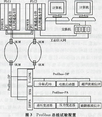
(2) Software configuration The operator station adopts Windows2000 operating system (Chinese), the system configuration software uses Siemens STEP7, and the fieldbus instrument management and diagnosis software uses SIMATIC PDM.
2.3.2 Information transmission test The performance of the DP and PA equipment and instruments were tested separately. The DP equipment is represented by a smart motor control and protection unit (SIMOCODE), and the PA meter is represented by a differential pressure transmitter.
2.3.2.1 Motor control and protection unit SIMOCODE has certain programming functions. It provides four truth tables, six trigger memories, two timers, and two counters, allowing the user to program it. SIMOCODE can not only perform simple functions such as start/stop and self-maintenance, but also the basic local protection control can be completed. SIMOCODE also has protection, alarm, and trip functions such as overload, soft start, and multiple startup curves, allowing the user to select the configuration.
SIMOCODE as slave on DP network, cyclic data communication: DP master instruction 4 bytes (Byte), feedback to DP master (4 to 12) bytes; acyclic data communication: standard DP protocol 20 bytes, DPVl extended protocol 213 bytes.
(1) 19-byte feedback information is defined in the cyclic communication data test test. The fixed information includes forward rotation, reverse rotation, stop, automatic/manual, overload alarm, electrical alarm, and electrical fault. The user-defined parts are allowed to: circuit breaker protection trip, abnormal circuit breaker failure, low bus voltage. These 3 custom signals are used as protection trip conditions and programmed in SIMOCODE to implement the in-place protection trip function. The analog information read in the test: motor current, motor start count, counter 1 value, counter 2 value, sensor value (motor coil thermal resistance). A one-byte DP master command was defined in the test to control the motor. For cyclic data communication, the PLC mapping address is configured, and cyclical reading, writing, and query of SIMOCODE are realized.
(2) Acyclic communication data test The standard DP protocol has a total of 20 bytes. Included status information is ground alarm/trip, overload alarm/trip, thermal resistance overtemperature alarm/trip, three-phase asymmetry and overload alarm/trip, motor blocked trip, PLC, CPU failure, etc.; analog information includes the most recent Overload trip current, cumulative number of overload trips, motor operating hours. Through the PLC programming and setting conditions, these data are read non-periodically into the buffer area for diagnosis, management, and parameter adjustment. 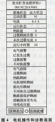
Using the above data, the motor operation and diagnostic functions of the Chinese interface were designed (Figure 4). The status and diagnostic information includes the data of the above cyclic and acyclic communication. The display is divided into three areas: the operating status section, the alarm status section, and the tripped fault status section.
2.3.2.2 Differential Pressure Transmitter (PA Meter)
The differential pressure transmitter's cyclic data communication can use 10 bytes, divided into 2 groups, representing the 2 physical quantities measured by the transmitter and their status. The first group of 5 bytes is the flow or differential pressure measurement (floating point) and its status, and the second group of 5 bytes is the differential pressure or temperature measurement and its status. A total of 8 status bytes are divided into 3 segments, which represent three states of good or bad measured values ​​or uncertain values, and are subdivided into multiple sub-states in each state. According to the transmitter's cyclical data communication, the Chinese interface status and diagnostics information window was designed (Figure 5). "Good quality" sub-states include normal, high/high 2 alarms, low/low 2 alarms, and event updates; "bad quality" sub-states include setup errors, equipment failures; "value uncertain" sub-states include violations Fixed value range, device restart for update, manual simulation status, compensated sensor failure, etc. 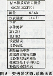
The reading and writing of non-cyclic data of PA instruments is more complicated and special software is needed, such as Siemens' equipment management software PDM. The magnetic flap level transmitter's cyclic data communication is 5 bytes, which is a floating-point measurement and an 8-bit status byte. The definition of the status byte is similar to that of a differential pressure transmitter.
2.3.3 Characteristics of Engineering Applications Through the above tests, the practical application of Profibus fieldbus has been confirmed.
System Structure: The redundant DP halo connects to the master station (PLC) and each DP branch linker slave station serves as the system master control communication network (up to 12Mb/s). The DP branch linker is distributed on the site and it sends DP. Branches (187.2kb/s to 1.5Mb/s) connect DP field instruments, equipment, and PA meters to form a device-level communications network. The PLC and operator stations and engineering stations use Industrial Ethernet (1OOMb/s) as the workshop monitoring communication network.
System function implementation and software: Traditional functions such as control, data acquisition, etc. are mainly implemented in the PLC. The use of Profibus cyclic data communication and some non-cyclic data communication to develop Chinese interface instrumentation, device diagnostics, and remote parameterization capabilities. Use the device management software PDM to implement remote parameter tuning and programming for PA instruments and SIMOCODE.
System design and installation: The cable design, laying and wiring installation are greatly reduced. If a motor is controlled in a traditional DCS design, there are 6 switching quantities and 1 analog quantity, and 7 cables are required. After adopting SIMO-CIDE-DP, at least 10 motor control and protection units can be connected to each DP branch. , The wiring quantity is 1/70 of the traditional DCS wiring. A solenoid valve box has 2 double electric control and 6 single electric control solenoid valves. The traditional PLC design requires 1O DO and 16 DI signals. After DP remote I/O and valve terminal, a DP branch is used. According to the four electromagnetic valve box (preferably 8 to 10), the wiring quantity is only 1/104 of the traditional PLC design. The drastic reduction in cabling has greatly reduced the workload of design, field installation and commissioning.
III. Conclusion Through the experimental research on the application of FF and Profibus fieldbus for engineering purposes, the FCS test system for a large thermal power plant water treatment control system has been constructed and can be directly applied to engineering practice. The field bus can make the power plant control system highly informatized and intelligent, and overall save (design, equipment, materials, wiring, construction, maintenance, etc.) throughout the entire life cycle of the system, and the greater the scale of the system, the more obvious its superiority.
Application of FF and Profibus Fieldbus in Thermal Power Plant
I. Application Research of Foundation Fieldbus FF (FoudationFieldbus) 1.1 Foundation Fieldbus Overview FOUNDATION fieldbus is a kind of field bus designed for important real-time control applications in industrial processes. It contains H1 (31.25kb/s) low-speed bus and HSE (HighSpeed ​​Ethernet, l00Mb/s) high-speed bus. Hl is more considered from industrial processes and DCS applications and is developed to meet the communication needs of field instruments and simple control loops. Hl bus baud rate is low, it is difficult to meet the requirements of large systems, can not meet the needs of the rapid process of manufacturing industry; HSE is an Ethernet-based high-speed field bus, and it can form a two-stage communication network with Hl, to achieve large-scale real-time system Control and information management functions.